MVE TEC3000 Controller
Preventative Maintenance
Preventative Maintenance Schedule
This section describes the preventative maintenance that should be performed on MVE freezers to ensure optimum operation and performance, as well as maximum service life. As with any technical piece of laboratory equipment, preventative maintenance is key to equipment success.
NOTE: This is the MVE recommended preventative maintenance. MVE Distributors may have a more comprehensive maintenance/service plan. At the minimum, the below schedule should be followed
Weekly
- Level Verification
- Verify Adequate Supply
Monthly
- Plumbing Leak Check
6 Months
- High Temp Alarm Test
- Level Alarm Test
- Thaw Freezer Lid
- Folding Step Inspection
- Lid Hinge Inspection
12 Months
- Inline Filter Replacement
- Complete Function Test
24 Months
- Solenoid Valve Replacement (Fill, Bypass, Purge)
- Relief Valve Replacement
- Lid Gasket Replacement
60 Months
- Complete Freezer Thaw and Moisture Removal
- Backup Battery Replacement
Preventative Maintenance Procedures
Level Verification
The differential pressure measurement system used on MVE freezers is nearly maintenance free. It provides a high level of accuracy and resolution to give the operator a precise indication of the exact amount of LN2 present in the freezer at all times. Despite its reliability, it is important that the accuracy of the level measurement system is verified on a weekly basis. This will prevent a control system malfunction from adversely affecting the temperature in the freezer storage space. Use the meter dipstick provided with every MVE freezer to manually measure the amount of LN2 in the freezer. Follow the "Dip Stick Procedure" to properly measure the level. If the level is off by 1.0 inch (25mm) or more, follow the calibration procedure.
Verify Adequate Supply
Adequate LN2 supply pressure and flow is imperative to the proper operation of MVE freezers. Any LN2 supply whether from bulk tank or liquid cylinder must be able to maintain a pressure of 22-35 psi (1.52 2.41 bar) during a filling cycle, and must have enough liquid to ensure the completion of a fill cycle. The majority of nuisance alarms reported from MVE freezers are due to inadequate supply.
Observe the pressure of the supply source. Ideally, pressure should be 22 35 psi (1.52-2.41 bars).
NOTE: It is very common for the pressure gauge on an industrial liquid cylinder to be inoperative. If you suspect this to be the case, install a pressure gauge inline between the liquid cylinder and the freezer for verification]
- Verify the amount of liquid in the supply source. Most bulk tanks have some method of digital or analog volume measurement. Liquid cylinders typically use a sight gauge. As with the pressure gauge on liquid cylinders, it is common for the sight gauge to be inoperative.
- The minimum amount of liquid necessary in the supply should be enough to completely fill the number of freezers it is supplying. This amount can be determined from the LN2 inch to volume table in the Appendix.
- Initiate a fill start on at least one freezer on the network. The supply system should be able to maintain appropriate pressure throughout the duration of the fill cycle.
- If the supply is determined to be inadequate, have your gas supplier replenish/replace the supply.
Plumbing Leak Check
Leaking plumbing connections can create a host of problems including but not limited to:
- Slow fill times
- Nuisance Alarms
- High LN2 Consumption
- Inaccurate level readings
- Inaccurate liquid usage readings
Leaking plumbing connections are especially common on liquid cylinder supply systems, since the fittings are regularly loosened and tightened during liquid cylinder swap out.
- With the supply system at operating pressure, thoroughly spray all transfer hose connections and freezer plumbing connections with leak detect solution
- Allow leak detect solution to penetrate fittings for at least 30 seconds
- Large leaks will be immediately apparent with large bubble formations
- Small leaks will take longer to detect, with small bubble formation in the appearance of foam
- Most leaks can be repaired by tightening the suspect fitting with a crescent or appropriate sized wrench.
- If tightening the fitting does not fix the leak, check the fitting for cracks and or galling. If the fitting is damaged, replace.
- Recheck any replaced fittings for leaks.
Level Alarm Test
The TEC 3000 control system can trigger a high level or low level alarm if the LN2 level in the freezer exceed the user defined parameters.
High Level Alarm Test:
- Observe and record the current LN2 level.
- Record the current level settings. They may be accessed by pressing the up and down arrow simultaneously to access the quick reference menu, or through the Liquid Level Menus. The current LN2 level should be between the High Level Alarm setting and Low Level Alarm setting. If not, allow the freezer to fill until it reaches the High Level Fill set point.
- Adjust the level offset so that the current level is a value that is greater than the High Level Alarm setting. For example, if the High Level Alarm setting is currently 10.0 inches, increase the offset value by at least 1.0 inch. This will "fool" the controller into thinking that the level inside the freezer is higher than actual.
- Observe the audible/visual alarm. Be aware that the level alarms have one minute. This delay is intentional and is to prevent nuisance alarms.
- If the alarm does not occur after one minute, verify that the audible alarm is turned on.
- Decrease the offset value to the original observed setting.
Low Level Alarm Test (Stand Alone TEC 3000 configuration):
- Observe and record the current LN2 level.
- Remove the vinyl tube from the hose barb on the bottom of the TEC 3000. Be careful not to damage the tube.
- The displayed level should drop to 0.0 inches.
- After one minute, the audible alarm should sound.
- If the alarm does not sound, verify that the audible alarm is turned on.
- Reconnect the vinyl tube. If the tube is deformed at the end, it may be necessary to trim off 1/4" of the tube to ensure a good connection.
- Press "Fill" start to purge the level sensing line. After 30 seconds, the level should gradually increase to actual.
- After the fill cycle is complete, manually measure the level using the dipstick.
Low Level Alarm Test (Cabinet Model Freezers):
- Observe and record the current LN2 Level.
- Adjust the High Level Alarm setting to a value that is at least 5.0 inches higher than the current LN2 level. For example, if the current LN2 level is 5.0 inches, adjust the High Level Alarm setting to at least 10.0 inches.
- Adjust the High Level Fill setting to a value that is at least 4.0 inches higher than the current LN2 level.
- Adjust the Low Level Fill setting to a value that is at least 3.0 inches higher than the current LN2 level. If autofill is enabled, the freezer will begin filling automatically. Press "Fill Stop" to terminate the fill.
- Adjust the Low Level Alarm setting to a value that is at least 2.0 inches higher than the current LN2 Level.
- After one minute, the Low Level Alarm should sound.
- After alarm verification, return all level settings to their normal values.
Lid Thaw Procedure
- Open or remove lid from freezer. Depending on the freezer model, it may be necessary to remove the lid from the hinges for it to completely warm to room temperature.
- It is recommended that the freezer opening be covered with a spare lid or in another non- airtight manner to prevent moisture from entering the storage space and to minimize the top box temperature change while the lid is open.
- Allow lid to sit at room temperature for approximately 30 minutes.
- Once thawed, thoroughly dry lid, cork, and liner.
- Inspect lid for damage and replace parts if necessary.
Folding Step Inspection
MVE 1500 and 1800 series freezers equipped with folding steps assemblies should be inspected for integrity at least every 6 months. Verify that hinges and free of cracks and all connections are secure. Check that the anti-slip strips on the steps are in good condition and replace if necessary (PN 4810179). Ensure the step locking strap is able to securely hold the steps in their folded position. If the pivot bolts continuously loosen, apply thread locker (PN 11087674) and retighten.
Lid Hinge Inspection
MVE freezers with hinged lids should be inspected for integrity at least every 6 months. Verify that the hinges are free of damage and securely attached to the freezer and lid. MVE hinged freezers are counterbalanced for easy opening and closing. Ensure the lid opens smoothly to a near 90° angle. The lid should remain completely open without assistance. Ensure lid closes smoothly and comes to rest centered on the freezer. Adjust hinges or replace as needed. For part numbers, contact Customer/Technical Service with the freezer serial number.
Inline Filter Replacement
For Stock, HE, Cabinet, and MVE series:
CAUTION: Ensure that the LN2 supply valve is closed and the plumbing assembly is vented before removing the inline filter.
- Close the LN2 supply valve and disconnect the LN2 transfer hose from the plumbing assembly fill tee.
- Loosen and remove the fill tee and inline filter from the plumbing assembly.
- Replace the inline filter (PN 11648945) and reassemble the fill tee and filter to the plumbing assembly using new Teflon tape if needed. Ensure the filter is oriented correctly so that the affixed arrow indicates the direction of LN2 flow.
- Reconnect the LN2 transfer hose, open the LN2 supply valve and check fittings for any leaks.
For HEco series:
CAUTION: Ensure that the LN2 supply valve is closed and the plumbing assembly is vented before removing the inline filter.
- Close the LN2 supply valve and disconnect the LN2 transfer hose from the plumbing assembly fill tee.
- Using an adjustable wrench, loosen and remove the inline filter (Y Strainer PN 20669243).
- Clean/Replace the strainer as necessary. Reassemble the fill tee and filter to the plumbing assembly using Teflon tape if needed. Ensure the filter is oriented correctly.
- Reconnect the LN2 transfer hose, open the LN2 supply valve and check fittings for any leaks.
Complete Function Test
MVE recommends that freezers with TEC 3000 controllers undergo a complete function test every 12 months to ensure correct functionality and identify potential problems before symptoms develop. Function test documents can be written based on this manual or this manual itself can be used to verify the function of MVE freezers with TEC 3000 controllers.
Solenoid Valve Replacement
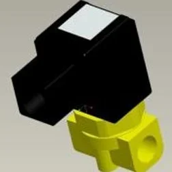
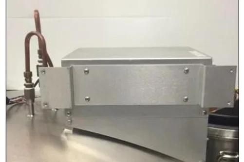
All MVE freezers are equipped with electromechanical solenoid valves that have been tested and approved by MVE for cryogenic use. These valves utilize a PTFE seal for optimal sealing in cryogenic environments. Over time, the normal thermal cycling that this seal is subject to will cause it to harden and lose its ability to seal completely. This will result in seepage past the sealing surface which can increase the LN2 consumption of the system, and in extreme cases result in an overfill situation. Thermal cycling through normal operation can also cause moisture ingress into the coil of the solenoid valve. Over time this may cause the connections and wiring in the coil to corrode and eventually fail. This will result in an inoperative solenoid valve.
NOTE: Over the life of MVE freezer, several different interchangeable 24VDC solenoids have been used. The current model is pictured below. Always use replacement solenoid valves from MVE. Substituting non MVE components may result in inoperable valves and even damage to the TEC 3000 control system. Damage to the control system due to use of non MVE parts will not be covered by warranty.
CAUTION: Ensure that the LN2 supply valve is closed and the plumbing assembly is vented before removing the solenoid valves.
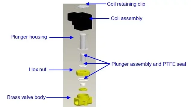
SMC (Black) Solenoid Valve Replacement
CAUTION: Ensure that the LN2 supply valve is closed and the plumbing assembly is vented before removing the solenoid valves.
- Remove plumbing shroud (on HE and HEco series) or rear access panel (on MVE series) to gain access to plumbing system.
- Remove coil retaining clip by inserting a flathead screwdriver between the clip and the edge of the coil body. Twist the screwdriver, and the clip should slide off.
- Remove and discard the coil assembly.
- Using a crescent wrench loosen hex nut and remove the plunger housing. Remove plunger housing and plunger assembly. Discard these parts.
- Remove any debris that may have collected in brass valve body.
- Inspect the brass valve body of the solenoid valve for nicks or damage. If the sealing surface appears to be in good condition, the valve body may be reused. If the sealing surface is damaged, the plumbing will need to be disassembled and the entire body will need to be replaced (this is not common).
- Disassemble a new SMC valve (PN 14224611S) using the above procedure.
- Install the new plunger, plunger housing, and coil assembly onto the old valve body.
- Assembly valve with new components in the reverse order.
- Verify that no leaks are present using leak detect solution.
- Open the LN2 supply valve and initiate a fill cycle be pressing "Fill Start." Allow the fill cycle to complete and verify that flow stops at the termination of the fill cycle.
NOTES:
- If the brass valve body requires replacing, the freezer plumbing will need to be disassembled and the entire valve replaced (PN 14224611S). It is typically easier to start disassembling the plumbing assembly beginning at the fill tee for fill valve replacement or the gas bypass muffler for gas bypass valve replacement.
- When installing a complete new valve, ensure it is oriented correctly. An "N" is engraved on the side of the SMC brass valve body. The valve should be installed so that this "N" is on the inlet side of the valve.
- If an older style solenoid requires replacing, the freezer plumbing will need to be disassembled and the entire valve replaced by the current production SMC solenoid valve (PN 14224611S). It is typically easier to start disassembling the plumbing assembly beginning at the fill tee for fill valve replacement or the gas bypass muffler for gas bypass valve replacement.
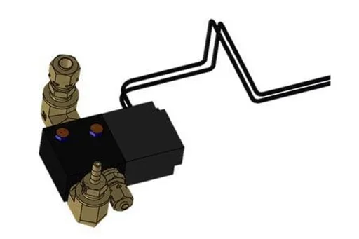
Purge Valve Replacement
CAUTION: Ensure that the LN2 supply valve is closed and the plumbing assembly is vented before removing the solenoid valves.
- Remove plumbing shroud (on HE and HEco series) or rear access panel (on MVE series) to gain access to plumbing system.
- Disconnect the Purge Valve wires from the TEC3000 wire harness.
- Using an adjustable wrench, disconnect the copper tubing from the 2 fittings on the Purge Valve assembly.
- Disconnect the clear vinyl tubing from the barbed fitting.
- Remove the two bolts that mount the Purge Valve to the plumbing platform.
- Repeat steps 1-5 in reverse order to install a new Purge Valve.
Relief Valve Replacement
CAUTION: Ensure that the LN2 supply valve is closed and the plumbing assembly is vented before removing the relief valve.
- Remove plumbing shroud (on HE series) to gain access to plumbing system.
- If equipped with a relief valve deflector, loosen the deflector clamp and slide off the deflector.
- Loosen the relief valve and remove it from the plumbing assembly. Be sure to support the attachment tube with wrench to prevent damage from twisting.
- Install new relief valve (PN 1810032) applying new Teflon tape if needed. Ensure relief valve is rated to 50 PSI (3.4 bar).
CAUTION: Installing a relief valve with a different pressure rating could prevent proper operation and lead to a dangerous over pressurized condition. Additionally, this will void any warranty.
Lid Gasket Replacement
The lid gasket configuration and material will vary depending on the freezer model and vintage. For the correct part numbers, contact Customer/Technical Service with the freezer serial number. There are three main types of lid gaskets and the replacement instructions for each are given below.
MVE High Efficiency/HEco Series
- Depending on the condition of the current gasket, the gasket material can be removed and replaced or more material can simply be added to the existing gasket.
- The replacement gasket material will be a neoprene tape.
- Simply clean the surfaces, remove the tape back to expose the adhesive and install gasket material.
- Trim to size as needed.
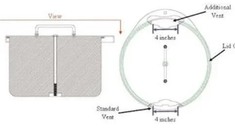
- Cut a 4 inch gap in the gasket material on either side of the lid as shown below to allow sufficient venting of the freezer space
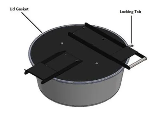
MVE Series/HEco and HE 1800 Series (Gasket with Trim Seal)
*Note: This gasket is also used on older XLC Freezers (230, 810, 1520).
- Clean the surfaces and remove the existing gasket.
- Trim new gasket to size as needed.
- Cut a horizontal slit into the gasket for the locking tab.
- Push new gasket firmly into position around the lid assembly.
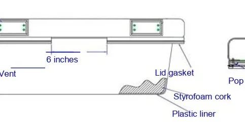
MVE and MVE Stock Series-Riveted Gasket
- Note how the current gasket is attached to the lid. The replacement gasket will be installed the same manner.
- If applicable, remove lid from hinges.
- Place the lid in the closed position.
- Remove spring pressure from the hinge by loosening the ½ inch nut on the rod inside the hinge body.
- Remove screws securing the hinges to the freezer lid.
- Remove lid assembly, and place it upside down either on top of the freezer opening or on flat surface.
- Using a 1/8 inch drill bit, carefully drill off the heads of the existing rivets holding the gasket to the lid.
- Remove gasket.
- Inspect plastic lid liner and Styrofoam cork for damage and replace if necessary.
- Install new gasket so that it lays flat and the flange is between the lid and the lid liner.
- Properly align lid liner so that the existing rivet holes can be reused.
- Insert 1/8 inch pop rivets into the existing liner holes, through the gasket, and then through the lid holes so that the fat part of the rivet is exposed. Sometimes it is easier to carefully drill through the gasket then inserting the rivets instead of attempting to puncture the gasket with the rivet.
- Using a pop rivet gun, securely rivet the liner and gasket to the freezer lid.
- Cut a 6 inch (150 mm) gap in the gasket at the rear of the freezer lid to allow the freezer space to vent.
- Reinstall lid.
- If applicable, reinstall lid hinges.
- With the lid closed, install and tighten screws securing hinges to the lid.
- Using the ½ inch deep well socket, increase spring pressure until the hinges will hold the lid at approximately a 45° angle.
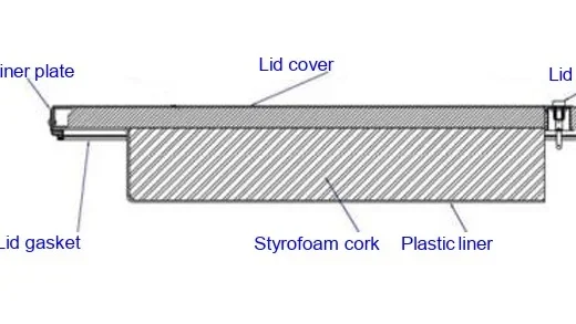
MVE Cabinet Series
- Remove lid from freezer hinges.
- Place the lid in the closed position.
- Remove spring pressure from the hinge by loosening the ½ inch nut on the rod inside the hinge body.
- Remove screws securing the hinges to the freezer lid.
- Remove liner retainer plate from the back of the lid.
- Slide the plastic liner and plate assembly out through the back of the lid.
- Note how the current gasket is installed. The replacement gasket will be installed in the same manner.
- Separate the plastic liner from the plate.
- Remove gasket.
- Inspect plastic liner and Styrofoam cork for damage and replace if necessary.
- Install new gasket in the same manner between the liner and plate.
- Slide plastic liner and plate assembly back into the lid.
- Cut a 6 inch (150 mm) gap in the gasket at the back of the lid to allow sufficient venting.
- Reinstall lid hinges.
- With the lid closed, install and tighten screws securing hinges to the lid.
- Using the ½ inch deep well socket, increase spring pressure until the hinges will hold the lid at approximately a 45° angle.
Complete Freezer Thaw and Moisture Removal
- Remove freezer LN2 supply.
- Unplug TEC 3000 main power and battery backup if equipped.
- Open or remove lid from freezer.
- Allow LN2 to completely evaporate and the freezer space to warm to room temperature. Placing a fan blowing into the freezer will accelerate this process.
- After it has reached ambient temperature, thoroughly remove any moisture from the freezer space. This can be done with a wet/dry vacuum and towels. For High Efficiency models, open the hinged hatch on the bottom of the turn-tray to access the bottom of the freezer.
- Once moisture has been removed from the freezer space, purge the plumbing assembly and annular lines with nitrogen gas. Compressed nitrogen or the gas use valve on a LN2 cylinder work best. The LN2 cylinder vent valve can also work, but will deplete the cylinder head pressure quickly. Ensure the nitrogen gas pressure does not exceed 50 PSI (3.4 bar).
- Plug in the TEC 3000 main power and connect the freezer plumbing via transfer hose to a compressed nitrogen supply or the gas use valve on a LN2 cylinder. Ensure gas bypass is disabled if equipped.
- Press "Start Fill" and allow the freezer to fill for 30 seconds.
- Press "Stop Fill."
- Press "Start Fill" and allow the freezer to fill for 30 seconds.
- Continue cycling fills for 30 seconds until the plumbing assembly and annular lines are clear and completely dry.
In some cases, it may be necessary to purge the level sensing annular line separately. This can be done by connecting pressurized nitrogen gas directly to the freezer annular line fitting.
CAUTION: Ensure that the LN2 supply valve is closed and the plumbing assembly is vented before loosening the compression fitting and removing the annular line tube.
- Loosen and remove the 1/4 inch compression fittings from the purge valve and the freezer annular line fitting.
- Remove 1/4 inch copper tube and purge to clear any moisture.
- Connect nitrogen gas source directly to the freezer's 3/8 inch FPT annular line connection.
- Purge annular line with nitrogen gas, maintaining a pressure below 50 PSI (3.4 bar), until the line in clear and completely free of any moisture.
NOTE: If moisture is not completely removed for the freezer space and annular lines, ice will form when LN2 is reintroduced into the freezer. Ice blockage in the freezer space or annular lines will interfere with proper function of the freezer and level sensing system.
Ensure all moisture is completely removed prior to introducing LN2
Battery Backup Replacement and Installation
General
The freezer backup batteries (BB) can be replaced every five years or if the BB voltage has dropped below 21 VDC. The TEC3000 will start to lose functionality when the BB is below 18 VDC. To test any suspect BB, disconnect the AC power and allow freezer to run for 30 minutes; the power failure (PF) alarm should trigger. While it is still in PF alarm allow the freezer to perform a fill still using the BB, and once it has reached its high level set point measure the BB voltage. If the voltage measures 24 to 27 VDC the batteries are good. In any case, the best approach is to always replace a suspect battery or if the battery age is more than five years old.
- NOTE: New batteries may need to be charged for several hours before it is able to power the TEC3000. The TCE3000 will constantly monitor, charge, and sense the current in its battery circuit. With its main power connected, the TEC3000 will constantly produce a 27 VDC trickle charge to keep the batteries fully charged.
The installation procedure applies to the following models:
- HEco Series, Cabinet Series, and MVE (Open Tops) Series- Use Battery Backup PN: 11864171
- Vario Series, Stock Series, and High Efficiency Series- Use Battery Backup PN: 12885791
Each BB utilizes two internal batters (PN: 10718155). If performing preventative maintenance, then it is recommended to purchase 2x 10718155 and replace the internal batteries. See the Battery Replacement section below for replacement instructions.
Tools Required
Philips Screwdriver, Volt/Ohm Meter, Small Flat Head and Phillips Screw driver, Wire Ties
Unpacking
Unpack the assembly and inspect for damage. If any damage is found, a freight claim should be filed with the carrier as soon as possible. Inspect to insure that all parts of the assembly are included.
Battery Replacement
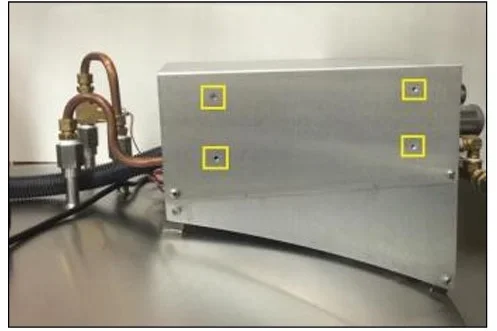
- Make sure the power supply and the battery backup are disconnected.
- Remove the battery backup assembly from the HE plumbing stack assembly by removing the four Phillips head screws; Note: if an MVE Series, the battery backup is mounted inside the rear cabinet.
- Remove the four Philips screws holding the backing plate
- Cut the plastic zip ties and remove the batteries noting the wire connection. Batteries are connected in series, - to + as shown in the below diagram.
- Ensure the cables are routed correctly.
- Reverse the removal procedure.
Battery Installation- Vario Series, Stock Series, and High Efficiency Series
Installing the Bracket for the Battery Backup
- Disconnect main power cord.
- Disconnect LN2 supply
- Use the 10-32 screws to install the bracket to the freezer on the plumbing stack cover.
Battery Installation- HEco Series, Cabinet Series, and MVE Series
Installing the Battery Backup
- Disconnect the main power cord.
- Disconnect LN2 supply.
- Before installing the battery backup on the freezer, measure the voltage at the end connector for approximately 24 VDC to 27 VDC.
- If no voltage is present, the included fuse must be installed before connecting the battery to the main wire harness.
- Open the battery enclosure and unscrew the fuse harness.
- Install the fuse.
- Close the fuse harness and the battery enclosure.
- With the fuse installed and the battery backup reading approximately 24-27VDC, locate the battery backup mounting location.
- For Cabinet Series and MVE (Open Top) Series, this will be on the back of the Freezer. Remove the rear panel of the cabinet. Remove screws securing purge coil clamps at the upper battery backup mount inside the rear enclosure.
- For HECo Series Freezers, the battery backup is located under the work platform.
- For Vario Series, Stock Series, and High Efficiency Series, the battery will be mounted to bracket installed.
- For all freezers (excluding HEco Series), fasten the battery backup to the mounting location using the screws included with the battery backup.
- Verify that the TEC 3000 Controller will power on using the AC Power Supply only. NOTE: Do not connect the battery backup to the main wire harness until the AC Power Supply has been verified to power up the controller.
- Connect the battery backup to the proper connector on the TEC 3000 Wiring Harness.
Battery Installation- HEco Series Freezers
HEco 800 Series
- The battery backup will be placed on the 4 studs already located on the freezer. These are located on the bottom side of the workstation platform.
- Open the workstation platform. First, loosen the Philips head screws that fasten it to the freezer.
- Locate the mounting location for installing the battery backup. It will mount to the studs.
- Remove nuts from studs.
- Place the battery backup on the studs with the washers between the battery backup and the platform. Position the battery backup with the pigtail facing towards the front of the freezer. Note: The battery backup is capable of being positioned with the pigtail facing forwards or backwards. It is recommended that the pigtail faces forward so the batteries inside the housing remain in an upright position.
- Fasten nuts to studs. This will secure the battery backup to the workstation on the freezer.
HEco 1500 Series
- The battery backup will be placed on the 4 studs already located on the freezer. These are located on the side of the workstation platform.
- Open the workstation platform where the controller panel is located by loosening the two Philips head screws. This is the panel on the right when facing front of the freezer.
- Remove the back control panel by removing the 4 screws holding it in place on the back of the workstation.
- Finding the mounting location to install the battery backup. This is on the side of the Plumbing Stack Cover.
- Remove the nuts from studs.
- Place the battery backup on the studs with the washers between the battery backup and the platform. Position the battery backup with the pigtail facing towards the front of the freezer. Note: The battery backup is capable of being positioned with the pigtail facing forwards or backwards. It is recommended that the pigtail faces forward so the batteries inside the housing remain in an upright position.
- Fasten nuts to studs. This will secure the battery backup to the workstation on the freezer.
- Reinstall the back control panel.
HEco 1800 Series
- The battery will be placed on the 4 studs located on the freezer. These are located on the side of the workstation platform.
- Open the workstation platform. First, loosen the Philips head screws that fasten it to the freezer.
- Locate the mounting location for installing the battery backup. It will mount to the studs.
- Remove nuts from studs.
- Place the battery backup on the bolts with the washers between the battery backup and the platform. Position the battery backup with the pigtail facing towards the front of the freezer. Note: The battery backup is capable of being positioned with the pigtail facing forwards or backwards. It is recommended that the pigtail faces forward so the batteries inside the housing remain in an upright position.
- Fasten nuts to studs. This will secure the battery backup to the workstation on the freezer.
- Verify that the TEC3000 Controller will power on using the AC Power Supply only. Note: Do not connect the battery backup to the main wire harness until the AC Power Supply has been verified to power up the controller.
- Connect the battery backup to the proper connector on the TEC3000 Wiring Harness.
- Adjust the TEC3000 setting to enable the battery backup feature.
HEco TEC3000 Replacement
Back Panel
- Disconnect the AC power cord from the back panel.
- Open the working platform.
- Disconnect the wiring harness from the plumbing connection interface.
- Disconnect Temp A and Temp B probes along with the power input cable from the back panel.
- Disconnect RJ45 cable from the front panel.
- Remove 4 Philips head screws from the faceplate of the back panel
- Note: The power supply connection port will be grounded to one of the philips head screws.
- Remove the clear vinyl tubing from the back panel.
- Gently remove the back panel from the working platform.
- To install a new black panel, repeat steps 1-8 in reverse order; ensuring that the power supply is grounded properly.
Front Panel
- Disconnect the AC power cord from the back panel.
- Open the working platform.
- Disconnect the hiring harness from the plumbing connection interface.
- Disconnect RJ45 cable from the front panel.
- Disconnect the front panel ground wire from the working platform and remove the 4 Philips head screws.
- Gently remove the front panel
- To install a new front panel, repeat steps 1-6 in reverse order, ensuring that the front panel is grounded properly.