Taylor Wharton
Changing Liquid Level
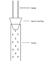
- The liquid level in the unit is determined by the position of the sensor probes in the sensor tube next to the fill tube. These probes have been set at installation to maintain a specific liquid level. The controller operates a fill cycle that adds liquid at low level, fills to a predetermined high level, then stops the fill. The cycle repeats when liquid drops to the low level over time.
- Sensor probe positions may be changed to define new high and low liquid levels, and these levels may be set independently to vary the liquid level differential between fills. If higher liquid level is desired, withdraw the sensor tube; for low level, the sensors must be moved further into (down) the sensor tube.
- Increasing the distance between low and high sensor probes allows greater liquid level fluctuation, less frequent filling and reduced fill losses; decreasing the distance has the opposite effect.
- To set the liquid level to a different point, or to change the level differential, the sensors must be repositioned. Their position within the sensor tube is held in place by the sensor tube plug, which is split to allow the sensor leads to pass through. The sensor tube plug holds the sensors at the position necessary to maintain specific liquid levels.
- Two different sensor heights are specified by their position within the sensor tube. The low and high sensor pods are separately positioned to set the liquid levels at which the controller will start or terminate each fill cycle. Insert the sensor leads into the perforated sensor tube to the desired height. Mark the sensor leads at the top of the sensor tube. Pull the leads out just enough to install the sensor tube plug around the marks on the sensor leads. Insert sensor plug securely into the mouth of the tube. Perform this operation carefully, so the sensor leads are not damaged.
- After repositioning sensors, check to be sure the sensor tube is secured to the fill tube and the sensor wires are dressed and clear of rack operation, and turn the controller on. The controller should fill the refrigerator to the new liquid level. After sensors are repositioned, the controller should maintain the liquid pool at the new operating level.
Note: The high level sensors must be at least 1.75 in. (5.1 cm) above the low level sensor pod.
Remote Alarm Connection
Relay connections are provided on an external for user installation of a remote alarm circuit. Wiring external power supply and alarm devices must be supplied by the user. During an alarm condition, contacts 1 & 2 are closed and contacts 2 & 3 are open.
Remote Alarm Connection on Taylor-Wharton Freezers
- Back panelson most Taylor-Wharton freezers are equipped with a 3 point electrical socket. The socket connects to а control board mounted, SPDT (single pole double throw)" relay, rated at 10 amps, 125 VAC.
- A Switchcraft plug (#05GM3M) connects to the socket. It is available with leads as Taylor-Wharton part #R06K-8C20. Approximately 9 of wire extend from the plug. The gray wire connect to Pin #1, orange wire to Pin #2 and the purple wire to Pin #3.
- For automatic dialers and other alarm systems that are alarmed on either a contact make or break:
- Alarm on Break: connect the orange wire to Pin #2 and purple wire on Pin #3.
- Alarm on Make: connect orange wire to Pin #2 and the gray wire to Pin #1.
Maintenance
LS Series CryoStorage Maintenance
Defrosting K Series CryoStorage System
All liquid nitrogen storage systems are subject to ice and frost buildup over time. Regular preventive maintenance programs should be instituted to remove ice and frost from the sensor and fill tubes and from the refrigerator lid.
Ice and frost build up in the sensor tube may result in false readings being relayed to the controller from the sensors. Ice can form a thermal barrier around a level sensor, rendering it insensitive to the temperature differences between vapor and liquid. Sensors and thermocouple should be removed regularly and inspected for ice and frost build up.
Note: Ice or frost in the sensor tube may restrict the movement of sensor probes in the tube. Do not pull excessively on the sensor wiring while attempting to change sensor position. It may be necessary to remove the fill tube and tube from the container and allow it to thaw before the sensors can be repositioned.
Ice and frost buildup in the fill tube may block the flow of liquid nitrogen into the refrigerator during fill. This blockage can result in the liquid level dropping to dangerously low levels, and may result in the Low Alarm sensor being activated. In addition, a fill line blockage may cause the low LN, Supply Alarm to be activated. If the fill line becomes blocked, it must be removed from the refrigerator, allowed to thaw to room temperature, and purged with dry nitrogen or oil-free dry air to remove all traces of moisture before being reinstalled.
Cleaning the K Series CryoStorage System
The vessel must be cleaned and sterilized, regardless of the type of stored product, prior to return to Taylor-Wharton for repair of maintenance.
Auto-Tend Controller Maintenance
WARNING: Unplug the transformer from the wall before proceeding with any repairs.
The Auto-Tend has been designed for easy setup and maintenance. All connectors on the controller are uniquely identified snap-on plugs. The sensor, assembly, solenoid valve, power, remote alarm and data lines can be connected or disconnected in seconds.
Installing the Sensor Probes
For procedures for installing the sensor probes refer to the section title Changing Liquid Level in this section of the manual.
Removing the Sensor Probes
Disconnect the sensor probe lead connection from the back of the controller. Remove the fill tube. Carefully remove the sensor tube plug from the sensor tube and remove the sensor leads from the plug.
Note: Ice or frost in the sensor tube may restrict the movement of the sensor probes in the tube. Do not pull excessively on the sensor wiring while attempting to remove sensors. It may be necessary to remove the sensor tube from the container and allot it to thaw before the sensors can be removed.
Removing the Solenoid Valve
Turn off valve from LN, Supply and disconnect transfer hose. Disconnect only the solenoid valve lead connection from the controller board.
To remove the solenoid valve, loosen the compression fitting that connects the fill tube. Unscrew the two (2) mounting screws that hold the solenoid valve to the solenoid bracket. Then remove the solenoid valve and its associated plumbing. Disconnect the plumbing from the inlet and outlet side of the solenoid valve.
Installing the Solenoid Valve
To install a new solenoid valve, attach the connecting plumbing to the inlet and outlet connections of the valve using Teflon tape.
Note: Arrow on Solenoid Valve indicates flow direction.
Position the solenoid valve onto the solenoid valve bracket and tighten the two (2) mounting screws. Attach the compression fitting to the fill tube. Reinstall transfer hose, open supply valve, and check for leaks.